EL TELSİZLERİ
.jpeg)
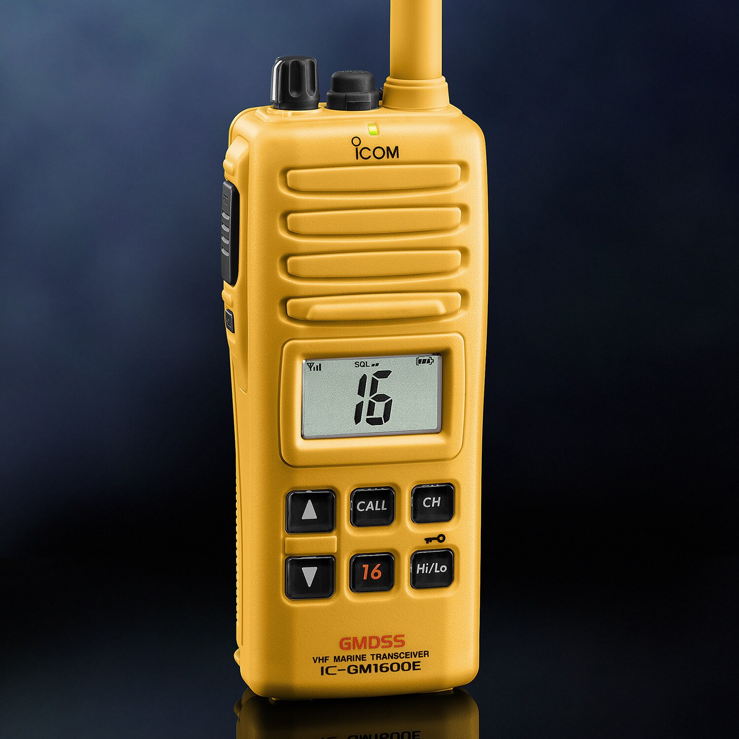
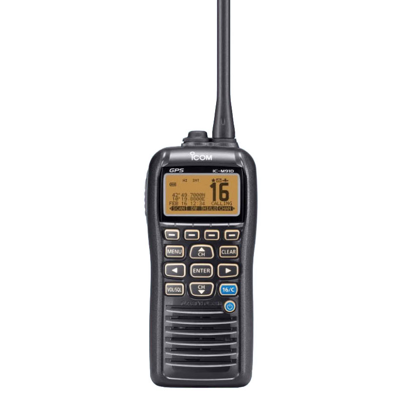
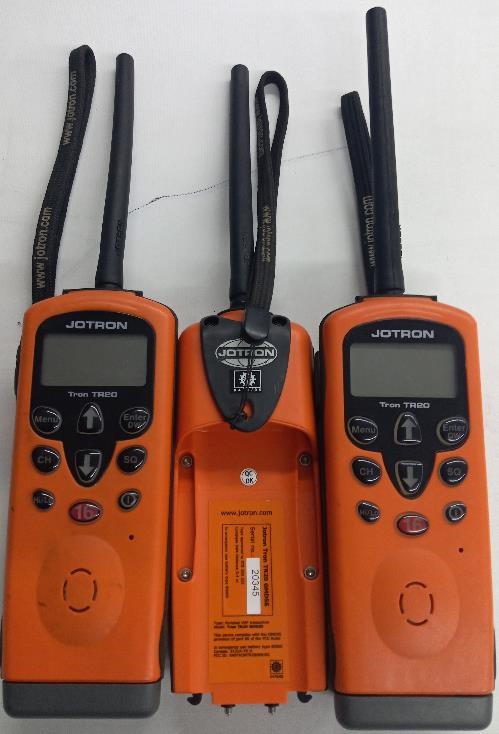
SIMRAD AXIS 50
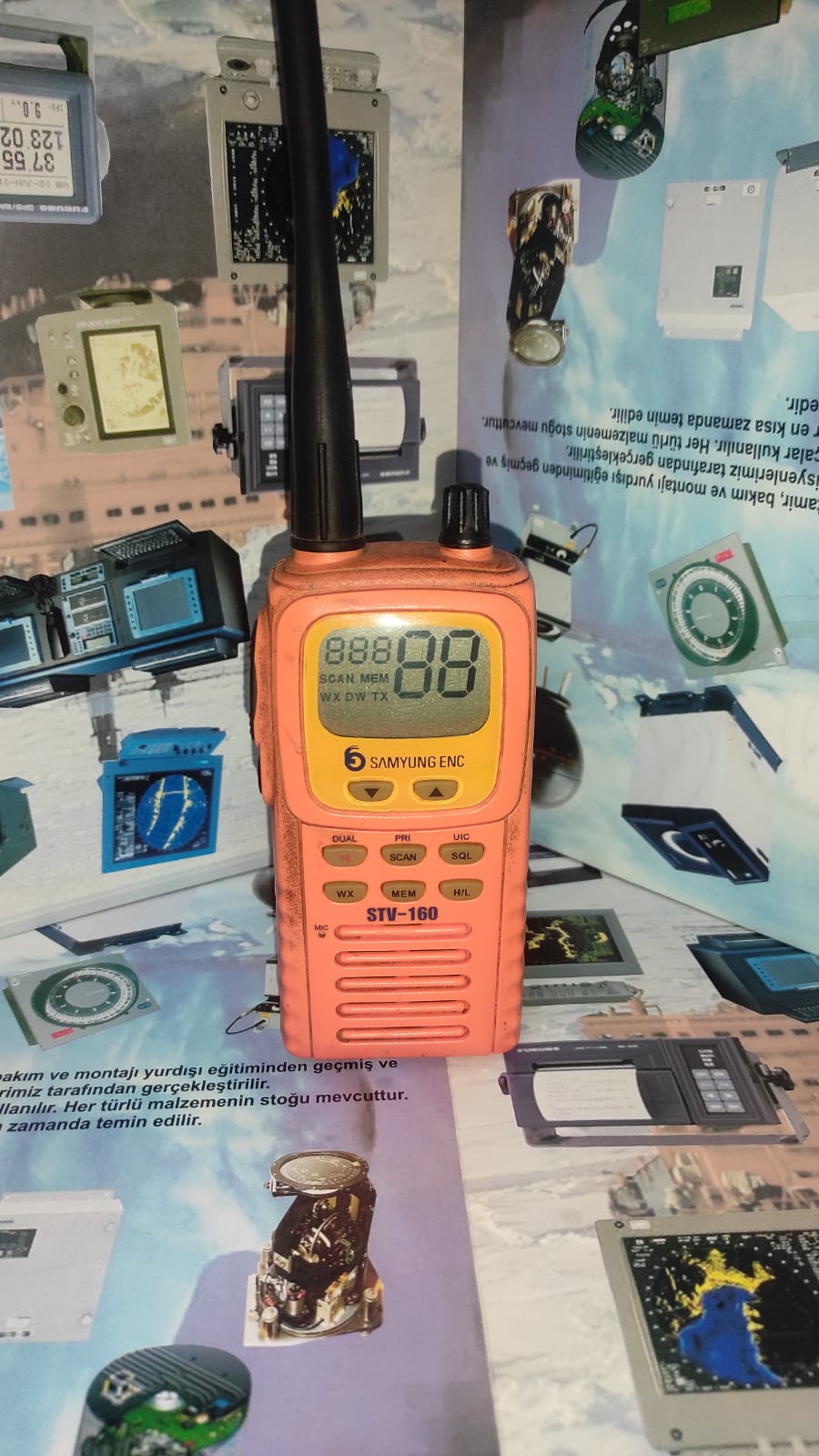
SAMYUNG STV -160
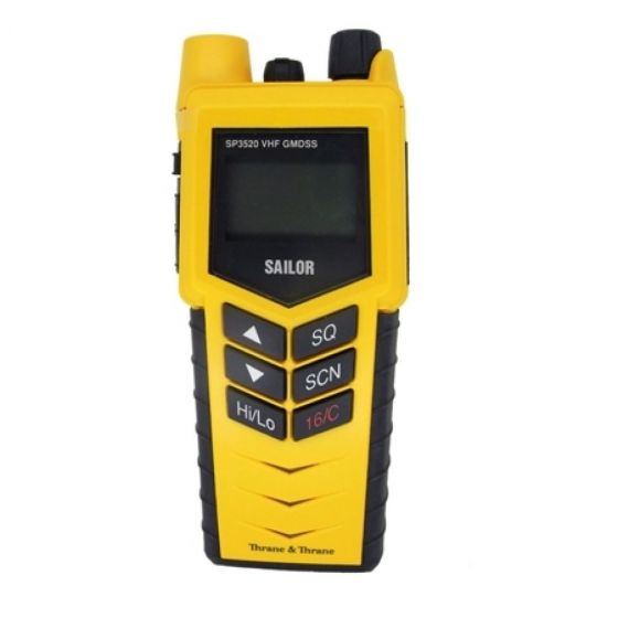
SAILOR SP 3520
İCOM C-M91D
JOTRON TRON 20
STOKLARIMIZ BU ÜRÜNLERLE SINIRLI DEĞİLDİR.
Benzer Ürünler

NORTHROP GRUMMAN SPERRY MARINE
NAVIGAT X MK 1
NAVIGAT X Mk 1/SR-180 Mk 1 is a microprocessor controlled gyrocompass system
with integrated automatic north speed error correction.
The system is type approved by the German Federal Maritime and Hydrographic
Agency (BSH) and complies with IMO resolutions A.424 (IX) and A.574 (14) as well
as DNV-W1 and ISO standard 8728.
For use in high speed craft, an optimized system is available, which complies with
IMO resolution A.821 (19) - HSC.
C. PLATH's unique method of supporting the gyrosphere by means of mere buoy-
ancy ensures north stabilization during short power failures. For example, after a
three minute loss of power, no more than two degrees of deviation may be expected.
Once power has been restored, the gyrocompass will return quickly to the correct
heading without requiring the usual settling period. The combined effects of the twin
rotors an the liquid damping system virtually eliminate latitude error.
Heading is measured as a 12 bit absolute value by means of a digital shaft encoder.
The high-speed follow-up system (>100%/sec.) ensures extremely accurate meas-
urements of heading and rate of turn under all operating conditions.
The system features an integrated TMC-function (magnetic compass transmission)
and input interfaces for a second gyrocompass, speed log, position receiver and two
rud angle feedback units.
The gyrocompass provides 12 independent serial data outputs to analogue or digital
repeaters (including short-circuit-proof 24 VDC repeater power supply), RS 422 and
NMEA sensor data outputs, a special NMEA Fast output interface (reduced dataset)
and a NMEA Superfast output interface (adjustable baudrate, max 38400 baud). Fur-
thermore, two 6 step/0 heading outputs, an analogue rate of turn output and an inter-
face for the voyage data printer NAVIPRINT are provided.
Integrated monitoring and alarm functions for the supply powers, gyroscope temperatur
and current and the follow-up system ensure secure and trouble-free operation of the
system.
The single unit design with a polyurethane hard foam housing of low weight allows
the gyrocompass system to be installed on any bridge, from large yachts to the most
capacious merchant vessels. If required, the integrated control and display unit may
be installed at a remote location from the gyrocompass or an additional remote oper-
ating unit installed.
As an option, a special "compass monitor" control unit is available, which provides
additional independent monitoring functions and features a numerical keypad, which
facilitates the operation of the system.
An optional switch-over unit for twin gyrocompass systems provides for complete
redundancy of all in- and output signals and thus ensures the independence of the
individual compasses.
Technical Data
heading display…………………………………………………………………………………………...4-digit
follow-up speed………………………………………………………………………………………. > 1007s
mean settling time………………………………………………………………………………………< 3h
freedom of roll and pitch………………………………………………………………………………. +40°
linear mean settle point error…………………………………………………………………………<0.1° sec lat
static error………………………………………………………………………………………………………<0.1° sec lat
dynamic error…………………………………………………………………………………………………< 0.4° sec lat
max.deviation after power interruption
of 3 min.................................................................................................................. < 2⁰
Ambient Temperature Range
operation............................................................................................................. .-10 - +55 °C
storage................................................................................................-25 - +70°C (w/o supporting fluid)
Power Supply supply voltage.............................................................................115/230 V~ ±10%;
including automatic switchover to 24 V emergency power supply in accordance with GMDSS rules for
INMARSAT/SES terminals or..................................................................................... .24VDC (18-36 V)
Protection Grade............................................................................. IP 23 in accordance with DIN 40050
Environmental Requirements and EMC.............................................. in accordance with IEC 945
Power Consumption DC AC
Start-up…………………………………………………………………………………………….80 W 125 VA
Operation…………………………………………………………………………………………..45 W 75 VA
Each analohue repeater……………………………………………………………………….7W7VA
Each digital repeater…………………………………………………………………………….7W7VA
Data Outputs
repeater outputs 12 (gyrocompass heading, magneticcompass heading, rate of turn, heading
reference status; supply power24 VDC, max. 7 W each)
data outputs NMEA (2gyrocompass heading, magnetic compass heading, rate of turn, position,
speed, heading reference status)
data outputs RS 422 3 (gyrocompass heading, magnetic compass heading, rate of turn, position,
speed, heading reference status, gyrocompass heading, magnetic)
Alarm and Status Outputs
Power failure / general device error alarm.... potential-free contact; max. 30W, 1 A; 125 V
AC power supply.......…....................................potential-free contact; max. 30W, 1 A; 125 V
AC power supply…………………………………………..potential-free contact; max. 30W, 1 A; 125 V
Heading reference status (G1/G2/Mag).......... potential-free contact; max. 30W, 1 A; 125 V
Heading difference alarm................................ potential-free contact; max. 30W, 1 A; 125 V
Max ROT alarm.........……………………………..….... potential-free contact; max. 30W, 1 A; 125 V
Watch alarm trigger output……………………….... potential-free contact; max. 30W, 1A; 125 V
Data and Signal Inputs
Magnetic Heading
Fluxgate sensor
Sin/Cos type or electronic compass
NMEA 0183 or PLATH-format
Heading Gyro 2
NMEA 0183
PLATH-format
Lehmkuhl LR 20 or LR 40
Position
NMEA 0183
Speed
NMEA 0183 or 200 pulses/nm
rudder angle 2
independent rudder angles
analogue (feedback, potentiometer)
Steering Mode
sei. switch status
Heading Reference Ext. (Gyro/Mag:G1/G2)
sei. switch status
Time Const. ROT
sei. switch status
Ext. Alarm Acknowledge
sei. switch status
NAVIGAT X MK 2 OPTIC
The NAVIGAT XMK2 is a microprocessor controlled gyrocompass system with
integrated automatic North speed error correction.
The single unit design with a polyurethane hard foam housing allows the gyro-
compass to be installed on any bridge. If required, an optional remote operat-
ing unit may be installed.
The unique method of supporting the gyrosphere by means of mere buoyancy
ensures North stabilization during short power failures. E.g., after a three
minute loss of power, no more than two degrees of deviation may be expected.
Once power has been restored, the gyrocompass will return quickly to the cor-
rect heading. The combined effects of the twin rotors and the liquid damping
system virtually eliminate latitude error.
Heading is measured as a 13-bit absolute value with a digital shaft encoder. The
high-speed follow-up system (follow-up speed upto 100%s) ensures that accu-
rate heading and rate of turn data is provided under all operating conditions.
Integrated monitoring of the supply powers, gyroscope current and the follow-
up system ensure secure and trouble-free operation.
Data and Signal Interfaces
The NAVIGAT XMK2 provides input interfaces for a magnetic compass (flux-
gate sensor or electronic compass), speed log and position receiver.
The system provides four serial data outputs to analogue or digital repeaters
(including short-circuit-proof 24 VDC repeater power supply), two RS422 sen-
sor data outputs, a Fast output interface (reduced dataset) and a Superfast out-
put interface (adjustable baudrate, max. 38400 baud).
Furthermore, a Furuno AD10 heading output, a 6 step/0 heading output, and an
analogue rate of turn output are provided. One sensor data output may be con-
figured to produce a graphical heading printout in conjunction with the nav.
data printer NAVIPRINT.
The NAVIGATXMK 2 may also be used as part of a component multicompass
system in conjunction with the Compass Monitor NAVITWIN III and a Switch-
Over Unit. In such a system, the Compass Monitor acts as the main heading
source selector and controls distribution of the compasses' output signals via
the Switch-Over Unit.
Technical Data
heading display……………………………………………………………………………..4-digit
max. follow-up speed……………………………………………………………………..100%
mean settling time………………………………………………………………………….. <3h
freedom of roll and pitch……………………………………………………………….. +40°
Accuracies
lin. mean settle point error………………………………………………………………< 0.1° sec lat
static error……………………………………………………………………………………..< 0.1° sec lat
dynamic error………………………………………………………………………………< 0.4° sec lat
deviation after 3 min. power interruption........................................... < 2 o
Environmental Requirements
ambient temperature, operation…………………………………………………………-10- +55 °C
ambient temperature, storage……………………………….......………-25-+70 °C (w/o supporting fluid)
protection grade…………………………………………………………………………….. IP 23 to DIN 40050
Environmental Requirements and EMC…………………………………………. in accordance w. IEC 60945
Power Supply:
supply voltages main 24 VDC (18-36 V),
backup 24 VDC (18-36 V);
including automatic switch-
over to 24 V backup supply
in accordance with GMDSS
rules for INMARSAT/SES
terminals
Max. Ripple Conten:
+4 Vpp; extreme values
may not exceed 36 V or fall
below 18V
Power Consumption
start-up……………………………………………………………….80W
operation................................................................45W
each analogue repeater………………………………………..7W
each digital repeater……………………………………………..7W
Dimensions and Weight
width.....................................................................404mm
height………………………………………………………………...520mm
depth………………………………………………………………..420mm
weight………………………………………..………………………..25kg
DATA OUTPUTS
Repeater (4x NMEA)
Gyrocompass heading
Magnetic compass heading
Rate of turn
Heading reference status
4x supply 24VDC
Max.7 W each
RS 422 SuperFast
Gyrocompass heading
Magnetic compass heading
Rate of turn
Heading reference status
6 Step Output
Act. Heading
Supply 24VDC max 18 W
AD10 Output
Gyrocompass heading
Rate of Turn, Analogue
+0.1-999,9mV/ O /min;
Max.10V, 10 mA
Navigation Data Printer
Graph: act. Headinh;
Text: date,time,heading
Reference,steering mode
Speed,position
Alarm and Status Outputs
Potential-free contact closures;
Max.30W, 125V/1A- each power failure/general device error heading difference alarm.
Data and Signal Inputs
Magnetic heading……………………………….NMEA 0183 or PLATH-format or NAVITWIN III or NAVIPILOT
Position……………………………………………… NMEA 0183
Speed………………………………………………… NMEA 0183 or 200 pulses/nm
Sterring mode……………………………………(auto/man) sei.switch status
Heading reference ext. (gyro/mag)…….sei.switch status
Ext.alarm acknowledge (mute)…………….sei.switch status
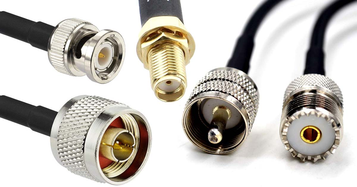
KONNEKTÖRLER
VHF Konnektör
UVHF Konnektör
BNC Konnektör
BNC Erkek Çevirici Konnektör
UHF Dişi Konnektör
STOKLARIMIZ BU ÜRÜNLERLE SINIRLI DEĞİLDİR.
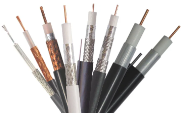
Anten Kabloları
RG58 Koaksiyel Kablo (Gps Anten Kablosu)
RG212 Koaksiyel Kablo (Anten Kablosu)
RG213 Koaksiyel Kablo (Anten Kablosu)
STOKLARIMIZ BU ÜRÜNLERLE SINIRLI DEĞİLDİR.

Marinelite
Marinelite Satellite SDME GSL9000
Marinelite Satellite SDME GSL1200
Marinelite SC9000 GNSS Compass
Marinelite Marine Anemometer MI9000S/SR
Marinelite GNSS Navigator GP9000
Marinelite Marine Radar
Marinelite SC120 Satellite Compass

ONWA
KP-38 GPS CHART PLOTTER (MULTI DISPLAY)
KW-360 ANEMOMETER
KM-8 GPS CHART PLOTTER (MULTI DISPLAY)
KP-38S GPS CHART PLOTTER
KM-12 GPS CHART PLOTTER (MULTI DISPLAY)

SAILOR
SAILOR VHF DSC 2048 (VHF DSC ,SAILOR)
SAILOR VHF 6222(VHF DSC ,SAILOR)
SAILOR VHF 5022(VHF DSC,SAILOR)
SAILOR MF/HF 6310(MF/HF ,SAILOR)
INMARSAT C 3606 DISPLAY(3606 DISPLAY INM-C)
SAILOR INMARSAT C SET SYSTEM(DISPLAY 6110,6110 ALARM PANEL,SAILOR H1252B/TT-3608A GMDSS PRİNTER,SAILOR 3022 TRANSCEİVER,INM C KEYBOARD)
STOKLARIMIZ BU ÜRÜNLERLE SINIRLI DEĞİLDİR.

KODEN
KODEN KGP 915 (GPS,KODEN)
KODEN KGP 913 (GPS,KODEN)
KODEN RADAR MDC - 2240 (KODEN RADAR UNIT)
KODEN ECHO SOUNDER CVS -126 (KODEN ECHO SOUNDER)
STOKLARIMIZ BU ÜRÜNLERLE SINIRLI DEĞİLDİR.

JRC
JRC AIS JHS-180 (AIS, Jrc)
JRC AIS JHS-182 (AIS, Jrc)
JRC AIS JHS-183 (AIS, Jrc)
JRC JHS 32 B (VHF, Jrc)
JHS 770 S (VHF, Jrc)
JRC NCR 333 (Navtex Receiver, Jrc)
JRC NCR 300-A (Navter, Jrc)
JRC ECHO SOUNDER JFE 380 (Echo Sounder, Jrc)
JRC JMA 2353 MK2 RADAR (Radar, Jrc)
JRC 5310 RADAR (Radar, Jrc)
JRC JUE 87 INM C (INMARSAT C,)
JRC NDF-268 (INM C KEYBOARD)
JRC JMA 1030 RADAR
JRC JMA 2144 RADAR
JRC JMA 5210 RADAR
JRC JMA 2343 RADAR
STOKLARIMIZ BU ÜRÜNLERLE SINIRLI DEĞİLDİR.
FURUNO
- Furuno 1416 Radar (Furuno, Radar, 1416)
- Furuno 1426 Radar (Furuno, Radar, 1426)
- Furuno FR-1505 MK3 Radar (Furuno, Radar, 1505)
- Furuno 1513BB Radar (Furuno, Radar, 1513)
- Furuno 1623 Radar (Furuno, Radar, 1623)
- Furuno 1715 Radar (Furuno, Radar, 1715)
- Furuno 1812 Radar (Furuno, Radar, 1812)
- Furuno 1815 Radar (Furuno, Radar, 1815)
- Furuno 1832 Radar (Furuno, Radar, 1832)
- Furuno 1835 Radar (Furuno, Radar, 1835)
- Furuno 1935 Radar (Furuno, Radar, 1935)
- Furuno 1942 MK2 Radar (Furuno, Radar, 1942, MK2)
- Furuno 1945 MK2 Radar (Furuno, Radar, 1945, MK2)
- Furuno 2115 Radar (Furuno, Radar, 2115)
- Furuno 2117 Radar (Furuno, Radar, 2117)
- Furuno 2817 Radar (Furuno, Radar, 2817)
- Furuno FA-AIS 100 (Furuno, AIS, FA-100)
- Furuno FA-AIS 150 (Furuno, AIS, FA-100)
- Furuno FA-AIS 170 (Furuno, AIS, FA-100)
- Furuno EchoSounder FE-700 (Furuno, Echosounder, Transducer, FE-700)
- Furuno FM-8500 (Furuno, VHF, FM-8500)
- Furuno FM-8800 (Furuno, VHF, FM-8800)
- Furuno NX-700A (Furuno, Navtex, NX-700A)
- Furuno NX-300 (Furuno, Navtex, NX-300)
STOKLARIMIZ BU ÜRÜNLERLE SINIRLI DEĞİLDİR.

SAMYUNG
SAMYUNG SPR-1400 ( Gps, dgps, samyung )
SAMYUNG N 430 (Samyung, N-430)
SAMYUNG SI 30 A AIS (ais, automatic identification system, samyung, samyung ais)
SAMYUNG N 700 (Samyung, N-700)
SAMYUNG NF 700 (Samyung, NF-700)
SAMYUNG N 560 (Samyung, N-560)
SAMYUNG SNX -300 (Navtex, Samyung)
STOKLARIMIZ BU ÜRÜNLERLE SINIRLI DEĞİLDİR.

OVA
OVA Radar (OVA, Radar, Radar Antenna)
Ova AIS 9000 (Ova, AIS, AIS 9000)
Ova EchoSounder AS88S (Ova, Echosounder, AS88S)
Ova GP-90 GPS Antenna (Nmea 0183 GPS Antenna)
Ova MI-9000S (Marine anemometer)
Ova transducer
STOKLARIMIZ BU ÜRÜNLERLE SINIRLI DEĞİLDİR.

DANALEC
Danalec DM 8000 Ecdıs (Danalec, Ecdıs, DM 8000)
Danalec DM 100 VDR (Danalec, VDR, DM 100)
STOKLARIMIZ BU ÜRÜNLERLE SINIRLI DEĞİLDİR.

EPIRB VE SART
GME MT 603 406Mhz Float-Free Epirb (Gme, MT-603, EPIRB)
ACR GlobalFix iPro 406Mhz GPS Epirb (Acr, Gps Epirb, GlobalFix iPro)
Jotron Tron 60s Epirb (Jotron, Epirb, Jotron Tron, 60s)
Jotron Tron Sart 20 ( Jotron, Jotron Tron, Sart, Sart20)
Acr Pathfinder Pro Sart (Acr, Sart, Pathfinder)
Acr pathfinder 3 Sart (ACR, Sart, Pathfinder)
GME SR500 SART (Gme, SR500, SART)
STOKLARIMIZ BU ÜRÜNLERLE SINIRLI DEĞİLDİR.
IXBLUE
IXBLUE Quadrans Compact IMO Gyrocompass and AHRS (ixblue, Quadrans, Gyro, Gyrocompass)
IXBLUE Octans Surface Survey-Grade Gyrocompass for Navigation & Dynamic Positioning (ixblue, Octans, Gyro, Gyrocompass)
STOKLARIMIZ BU ÜRÜNLERLE SINIRLI DEĞİLDİR.

RUSSIAN
- - Kurs 3, Kurs 4
- - Amur M
- - Amur 3M
- STOKLARIMIZ BU ÜRÜNLERLE SINIRLI DEĞİLDİR.

TOKIMEC TOKYO KEIKI
- - TG 8000 ES-110 GM-20
- - TG 6000 ES-140 GM-21
- - TG 5000 ES-160
- - TG 3000
- - PR-1500, PR-2000, PR-6000
- STOKLARIMIZ BU ÜRÜNLERLE SINIRLI DEĞİLDİR.

YOKOGAWA
ABOUT CMZ-900 GYROCOMPASS
GENERAL
A gyrocompass detectes the true north by means of a fast-spinning rotor, which is suspended with no friction
and is influenced by gravity and rotation of the Earth. A gyrocompass consequently indicaes ship’s heading.
CMZ900 series has been type approved in accordance with International Maritime Organization (IMO)
standarts.
FEATURES
1) A modular design saves the space. Master compass can be integrated in the autopilot steering stand.
2) Manual speed error correction.
3) External heading sensor can back up the heading outputs.
4) Serial data output IEC 61162-2 (high-speed transmission)
5) A unique anti-vibration mechanism enhanced by the velocity damping effect of high viscous oil, provides
superior damping of vibration and decoupling of shock at sea.
6) A small and lightweight container enchances the follow up speed. The gyrocompass reading changes
smoothly and does not lag when a small ship rapidly changes course.
7) Easy maintenance and long maintance periods.
- Titanium capsule and electrodes are employed at lower hemisphere of Gyrosphere. Purity is maintained
inside of the container, and maintance invertal is then longer-dated.
- The container id divided into two pieces at bottom when overhauled. Ship’s crew can replace Gyrosphere in
case of emergency.
8) The restart time can be preset from 1 to 99 hours.
MAIN FUNCTIONS
- Power supply: 24V DC and/or 100V to 220AC
- Heading outputs
- Serial data: 3 circuits
- Steppers: 1 circuit (0.3A max)
- Repeaters compasses:3 circuits
- Analog ROT: 3 circuits
- External headings sensor:1 circuit (Back-up of the heading outputs)
- Manuel speed error correction
POWER SUPPLY
- 24V DC (20V to 30V DC) and/or 100V/110V/115V/220V,AC,50/60Hz, shingle-phase
(MKR0207 AC adapter is required.)
SIGNALS
Serial interface: IEC6112-1
Transmission convention: Serial asynchronous form
Signaling rate: 4800bps
HDT heading true
THS True heading and status
HDG Heading deviation and variation
HDM heading/ROT (yokogowa inherent)
PERFORMANCE SPECIFICATIONS
1) Settling time: Within 5 hours (Usable accuracy in approx. 2 hours)
2) Accuracy
-Static:+025°xsecLat.(Lat=latitude)
-Dynamic:+0.75°secLat.(Lat=latitude)
3) Follow-up accuracy :0.1° or less
4) Maximum follow-up speed: 30%s
ENVIRONMENTAL CONDITIONS
1) Permissible roll and pitch angle +40 o
2) Permissible vibration
0 to 8.3H z 3mmP-P or less
8.3 to 25H z 0.35mmP-P or less
25 to 50H z 0.1mmP-P or less
3) Permissible ambient tempature
Master compass: -15 o C to +55 o C
Master compass: -10 o C to +50 o C (Operating)
Bearing repeater compass: -25 o C to +70 o C
4)EMC:IEC 60945 4th edition
We can supply to world wide and we can give service in all Turkey ports. Keep in touch with us.

AMI S-VDR
- - Wıht Amı Float Free Capsul
- - Wıht Amı Fixed Capsule
- - (Sımplıfıed) Wıth Amı Fixed Capsule
- - Ecdis Video Capture Card Kit
- - VDR SURVEY
- - VDR APT
STOKLARIMIZ BU ÜRÜNLERLE SINIRLI DEĞİLDİR.
MICRO TECHNICA VE DİĞER
- - Sirius MK2
- - Poloris
- - Arma Brown
- - SG 1000
- - SG Brown Meridian
STOKLARIMIZ BU ÜRÜNLERLE SINIRLI DEĞİLDİR.

RAYTHEON ANSCHÜTZ KIEL
- - Anschütz STD 4 (Anschutz, Gyrocompass, Standart 4, Std4)
- - Anschütz STD 6 (Anschutz, Gyrocompass, Standart 6, Std6)
- - Anschütz STD 12 (Anschutz, Gyrocompass, Standart 12, Std12)
- - Anschütz STD 14 (Anschutz, Gyrocompass, Standart 14, Std14)
- - Autopilot NautoPilot 5000
- - Autopilot NautoPilot 20X5
- - Autopilot PilotStar D
- - Autopilot NautoPilot 60
- - Anschütz NautoPilot D
- -Anschutz Repeater 133-302 (Anschutz Kiel, 133-302, Gyrocompass, Raytheon, Repeater, Tochterkompass)
- -Anschütz STD 20 (Anschutz, Gyrocompass, Standart 20, Std20)
- -Anschütz Gyrostar
- -Anschütz STD 22 (Anschutz, Gyrocompass, Standart 22, Std22)
- -Gyrocompass Repeater Unit 133-560 (Repeater, Raytheon, Anschutz Kiel, 133-560, Gyro)
- -Standart 22 and Standart 20 Gyrosphere (111006E01AT, Anschutz Kiel, Gyrocompass, Standart22, Std22, Standart20, Std20)
- -Standart 22 Gyrocompass Sensor PCB 110-222.101 (Anchutz Kiel, Pcb, Sensor, Standart 22, Std22)
- -Standart 22 Gyrocompass Connection Pcb NB05-356.E10 (Anschutz Kiel, Connection, Gyrocompass, Standart 22, Std22)
- -Standart 22 Gyrocompass Outer Sphere Pcb 110-233.101 E10 (Anschutz, Gyrocompass, Standart 22, Outer Sphere, Std22)
- -Standart 22 Gyrocompass Container (Anschutz, Container, Gyro, Gyrocompass)
- -Gyrocompass Annual Inspection Service Kit (Gyro, Gyrocompass, Standart 22, Std22)
STOKLARIMIZ BU ÜRÜNLERLE SINIRLI DEĞİLDİR.
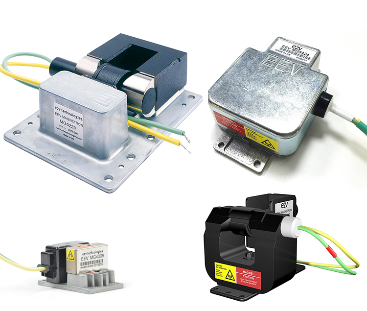
Magnetronlar
MSF 1425A 12.5 KW
MSF 1421B
MSF 1425B 12.5 KW
MG 5241F 12.5 KW
MG 5424 X BAND 25 KW
MG 5241 12.5 KW
MG 5241/4010 12.5 KW
E3571/MG4004
E3571 3 KW
JRC M14 M1437 25 KW
JRC M1315 / JP 9-2.5D 8 KW ,
STOKLARIMIZ BU ÜRÜNLERLE SINIRLI DEĞİLDİR.
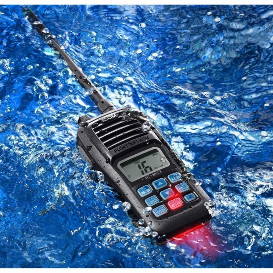
EL TELSİZLERİ
SIMRAD AXIS 50
SAMYUNG STV -160
SAILOR SP 3520
İCOM C-M91D
JOTRON TRON 20
STOKLARIMIZ BU ÜRÜNLERLE SINIRLI DEĞİLDİR.
NORTHROP GRUMMAN SPERRY MARINE
NAVIGAT X MK 1
NAVIGAT X Mk 1/SR-180 Mk 1 is a microprocessor controlled gyrocompass system
with integrated automatic north speed error correction.
The system is type approved by the German Federal Maritime and Hydrographic
Agency (BSH) and complies with IMO resolutions A.424 (IX) and A.574 (14) as well
as DNV-W1 and ISO standard 8728.
For use in high speed craft, an optimized system is available, which complies with
IMO resolution A.821 (19) - HSC.
C. PLATH's unique method of supporting the gyrosphere by means of mere buoy-
ancy ensures north stabilization during short power failures. For example, after a
three minute loss of power, no more than two degrees of deviation may be expected.
Once power has been restored, the gyrocompass will return quickly to the correct
heading without requiring the usual settling period. The combined effects of the twin
rotors an the liquid damping system virtually eliminate latitude error.
Heading is measured as a 12 bit absolute value by means of a digital shaft encoder.
The high-speed follow-up system (>100%/sec.) ensures extremely accurate meas-
urements of heading and rate of turn under all operating conditions.
The system features an integrated TMC-function (magnetic compass transmission)
and input interfaces for a second gyrocompass, speed log, position receiver and two
rud angle feedback units.
The gyrocompass provides 12 independent serial data outputs to analogue or digital
repeaters (including short-circuit-proof 24 VDC repeater power supply), RS 422 and
NMEA sensor data outputs, a special NMEA Fast output interface (reduced dataset)
and a NMEA Superfast output interface (adjustable baudrate, max 38400 baud). Fur-
thermore, two 6 step/0 heading outputs, an analogue rate of turn output and an inter-
face for the voyage data printer NAVIPRINT are provided.
Integrated monitoring and alarm functions for the supply powers, gyroscope temperatur
and current and the follow-up system ensure secure and trouble-free operation of the
system.
The single unit design with a polyurethane hard foam housing of low weight allows
the gyrocompass system to be installed on any bridge, from large yachts to the most
capacious merchant vessels. If required, the integrated control and display unit may
be installed at a remote location from the gyrocompass or an additional remote oper-
ating unit installed.
As an option, a special "compass monitor" control unit is available, which provides
additional independent monitoring functions and features a numerical keypad, which
facilitates the operation of the system.
An optional switch-over unit for twin gyrocompass systems provides for complete
redundancy of all in- and output signals and thus ensures the independence of the
individual compasses.
Technical Data
heading display…………………………………………………………………………………………...4-digit
follow-up speed………………………………………………………………………………………. > 1007s
mean settling time………………………………………………………………………………………< 3h
freedom of roll and pitch………………………………………………………………………………. +40°
linear mean settle point error…………………………………………………………………………<0.1° sec lat
static error………………………………………………………………………………………………………<0.1° sec lat
dynamic error…………………………………………………………………………………………………< 0.4° sec lat
max.deviation after power interruption
of 3 min.................................................................................................................. < 2⁰
Ambient Temperature Range
operation............................................................................................................. .-10 - +55 °C
storage................................................................................................-25 - +70°C (w/o supporting fluid)
Power Supply supply voltage.............................................................................115/230 V~ ±10%;
including automatic switchover to 24 V emergency power supply in accordance with GMDSS rules for
INMARSAT/SES terminals or..................................................................................... .24VDC (18-36 V)
Protection Grade............................................................................. IP 23 in accordance with DIN 40050
Environmental Requirements and EMC.............................................. in accordance with IEC 945
Power Consumption DC AC
Start-up…………………………………………………………………………………………….80 W 125 VA
Operation…………………………………………………………………………………………..45 W 75 VA
Each analohue repeater……………………………………………………………………….7W7VA
Each digital repeater…………………………………………………………………………….7W7VA
Data Outputs
repeater outputs 12 (gyrocompass heading, magneticcompass heading, rate of turn, heading
reference status; supply power24 VDC, max. 7 W each)
data outputs NMEA (2gyrocompass heading, magnetic compass heading, rate of turn, position,
speed, heading reference status)
data outputs RS 422 3 (gyrocompass heading, magnetic compass heading, rate of turn, position,
speed, heading reference status, gyrocompass heading, magnetic)
Alarm and Status Outputs
Power failure / general device error alarm.... potential-free contact; max. 30W, 1 A; 125 V
AC power supply.......…....................................potential-free contact; max. 30W, 1 A; 125 V
AC power supply…………………………………………..potential-free contact; max. 30W, 1 A; 125 V
Heading reference status (G1/G2/Mag).......... potential-free contact; max. 30W, 1 A; 125 V
Heading difference alarm................................ potential-free contact; max. 30W, 1 A; 125 V
Max ROT alarm.........……………………………..….... potential-free contact; max. 30W, 1 A; 125 V
Watch alarm trigger output……………………….... potential-free contact; max. 30W, 1A; 125 V
Data and Signal Inputs
Magnetic Heading
Fluxgate sensor
Sin/Cos type or electronic compass
NMEA 0183 or PLATH-format
Heading Gyro 2
NMEA 0183
PLATH-format
Lehmkuhl LR 20 or LR 40
Position
NMEA 0183
Speed
NMEA 0183 or 200 pulses/nm
rudder angle 2
independent rudder angles
analogue (feedback, potentiometer)
Steering Mode
sei. switch status
Heading Reference Ext. (Gyro/Mag:G1/G2)
sei. switch status
Time Const. ROT
sei. switch status
Ext. Alarm Acknowledge
sei. switch status
NAVIGAT X MK 2 OPTIC
The NAVIGAT XMK2 is a microprocessor controlled gyrocompass system with
integrated automatic North speed error correction.
The single unit design with a polyurethane hard foam housing allows the gyro-
compass to be installed on any bridge. If required, an optional remote operat-
ing unit may be installed.
The unique method of supporting the gyrosphere by means of mere buoyancy
ensures North stabilization during short power failures. E.g., after a three
minute loss of power, no more than two degrees of deviation may be expected.
Once power has been restored, the gyrocompass will return quickly to the cor-
rect heading. The combined effects of the twin rotors and the liquid damping
system virtually eliminate latitude error.
Heading is measured as a 13-bit absolute value with a digital shaft encoder. The
high-speed follow-up system (follow-up speed upto 100%s) ensures that accu-
rate heading and rate of turn data is provided under all operating conditions.
Integrated monitoring of the supply powers, gyroscope current and the follow-
up system ensure secure and trouble-free operation.
Data and Signal Interfaces
The NAVIGAT XMK2 provides input interfaces for a magnetic compass (flux-
gate sensor or electronic compass), speed log and position receiver.
The system provides four serial data outputs to analogue or digital repeaters
(including short-circuit-proof 24 VDC repeater power supply), two RS422 sen-
sor data outputs, a Fast output interface (reduced dataset) and a Superfast out-
put interface (adjustable baudrate, max. 38400 baud).
Furthermore, a Furuno AD10 heading output, a 6 step/0 heading output, and an
analogue rate of turn output are provided. One sensor data output may be con-
figured to produce a graphical heading printout in conjunction with the nav.
data printer NAVIPRINT.
The NAVIGATXMK 2 may also be used as part of a component multicompass
system in conjunction with the Compass Monitor NAVITWIN III and a Switch-
Over Unit. In such a system, the Compass Monitor acts as the main heading
source selector and controls distribution of the compasses' output signals via
the Switch-Over Unit.
Technical Data
heading display……………………………………………………………………………..4-digit
max. follow-up speed……………………………………………………………………..100%
mean settling time………………………………………………………………………….. <3h
freedom of roll and pitch……………………………………………………………….. +40°
Accuracies
lin. mean settle point error………………………………………………………………< 0.1° sec lat
static error……………………………………………………………………………………..< 0.1° sec lat
dynamic error………………………………………………………………………………< 0.4° sec lat
deviation after 3 min. power interruption........................................... < 2 o
Environmental Requirements
ambient temperature, operation…………………………………………………………-10- +55 °C
ambient temperature, storage……………………………….......………-25-+70 °C (w/o supporting fluid)
protection grade…………………………………………………………………………….. IP 23 to DIN 40050
Environmental Requirements and EMC…………………………………………. in accordance w. IEC 60945
Power Supply:
supply voltages main 24 VDC (18-36 V),
backup 24 VDC (18-36 V);
including automatic switch-
over to 24 V backup supply
in accordance with GMDSS
rules for INMARSAT/SES
terminals
Max. Ripple Conten:
+4 Vpp; extreme values
may not exceed 36 V or fall
below 18V
Power Consumption
start-up……………………………………………………………….80W
operation................................................................45W
each analogue repeater………………………………………..7W
each digital repeater……………………………………………..7W
Dimensions and Weight
width.....................................................................404mm
height………………………………………………………………...520mm
depth………………………………………………………………..420mm
weight………………………………………..………………………..25kg
DATA OUTPUTS
Repeater (4x NMEA)
Gyrocompass heading
Magnetic compass heading
Rate of turn
Heading reference status
4x supply 24VDC
Max.7 W each
RS 422 SuperFast
Gyrocompass heading
Magnetic compass heading
Rate of turn
Heading reference status
6 Step Output
Act. Heading
Supply 24VDC max 18 W
AD10 Output
Gyrocompass heading
Rate of Turn, Analogue
+0.1-999,9mV/ O /min;
Max.10V, 10 mA
Navigation Data Printer
Graph: act. Headinh;
Text: date,time,heading
Reference,steering mode
Speed,position
Alarm and Status Outputs
Potential-free contact closures;
Max.30W, 125V/1A- each power failure/general device error heading difference alarm.
Data and Signal Inputs
Magnetic heading……………………………….NMEA 0183 or PLATH-format or NAVITWIN III or NAVIPILOT
Position……………………………………………… NMEA 0183
Speed………………………………………………… NMEA 0183 or 200 pulses/nm
Sterring mode……………………………………(auto/man) sei.switch status
Heading reference ext. (gyro/mag)…….sei.switch status
Ext.alarm acknowledge (mute)…………….sei.switch status
KONNEKTÖRLER
VHF Konnektör
UVHF Konnektör
BNC Konnektör
BNC Erkek Çevirici Konnektör
UHF Dişi Konnektör
STOKLARIMIZ BU ÜRÜNLERLE SINIRLI DEĞİLDİR.
Anten Kabloları
RG58 Koaksiyel Kablo (Gps Anten Kablosu)
RG212 Koaksiyel Kablo (Anten Kablosu)
RG213 Koaksiyel Kablo (Anten Kablosu)
STOKLARIMIZ BU ÜRÜNLERLE SINIRLI DEĞİLDİR.
Marinelite
Marinelite Satellite SDME GSL9000
Marinelite Satellite SDME GSL1200
Marinelite SC9000 GNSS Compass
Marinelite Marine Anemometer MI9000S/SR
Marinelite GNSS Navigator GP9000
Marinelite Marine Radar
Marinelite SC120 Satellite Compass
ONWA
KP-38 GPS CHART PLOTTER (MULTI DISPLAY)
KW-360 ANEMOMETER
KM-8 GPS CHART PLOTTER (MULTI DISPLAY)
KP-38S GPS CHART PLOTTER
KM-12 GPS CHART PLOTTER (MULTI DISPLAY)
SAILOR
SAILOR VHF DSC 2048 (VHF DSC ,SAILOR)
SAILOR VHF 6222(VHF DSC ,SAILOR)
SAILOR VHF 5022(VHF DSC,SAILOR)
SAILOR MF/HF 6310(MF/HF ,SAILOR)
INMARSAT C 3606 DISPLAY(3606 DISPLAY INM-C)
SAILOR INMARSAT C SET SYSTEM(DISPLAY 6110,6110 ALARM PANEL,SAILOR H1252B/TT-3608A GMDSS PRİNTER,SAILOR 3022 TRANSCEİVER,INM C KEYBOARD)
STOKLARIMIZ BU ÜRÜNLERLE SINIRLI DEĞİLDİR.
KODEN
KODEN KGP 915 (GPS,KODEN)
KODEN KGP 913 (GPS,KODEN)
KODEN RADAR MDC - 2240 (KODEN RADAR UNIT)
KODEN ECHO SOUNDER CVS -126 (KODEN ECHO SOUNDER)
STOKLARIMIZ BU ÜRÜNLERLE SINIRLI DEĞİLDİR.
JRC
JRC AIS JHS-180 (AIS, Jrc)
JRC AIS JHS-182 (AIS, Jrc)
JRC AIS JHS-183 (AIS, Jrc)
JRC JHS 32 B (VHF, Jrc)
JHS 770 S (VHF, Jrc)
JRC NCR 333 (Navtex Receiver, Jrc)
JRC NCR 300-A (Navter, Jrc)
JRC ECHO SOUNDER JFE 380 (Echo Sounder, Jrc)
JRC JMA 2353 MK2 RADAR (Radar, Jrc)
JRC 5310 RADAR (Radar, Jrc)
JRC JUE 87 INM C (INMARSAT C,)
JRC NDF-268 (INM C KEYBOARD)
JRC JMA 1030 RADAR
JRC JMA 2144 RADAR
JRC JMA 5210 RADAR
JRC JMA 2343 RADAR
STOKLARIMIZ BU ÜRÜNLERLE SINIRLI DEĞİLDİR.
FURUNO
- Furuno 1416 Radar (Furuno, Radar, 1416)
- Furuno 1426 Radar (Furuno, Radar, 1426)
- Furuno FR-1505 MK3 Radar (Furuno, Radar, 1505)
- Furuno 1513BB Radar (Furuno, Radar, 1513)
- Furuno 1623 Radar (Furuno, Radar, 1623)
- Furuno 1715 Radar (Furuno, Radar, 1715)
- Furuno 1812 Radar (Furuno, Radar, 1812)
- Furuno 1815 Radar (Furuno, Radar, 1815)
- Furuno 1832 Radar (Furuno, Radar, 1832)
- Furuno 1835 Radar (Furuno, Radar, 1835)
- Furuno 1935 Radar (Furuno, Radar, 1935)
- Furuno 1942 MK2 Radar (Furuno, Radar, 1942, MK2)
- Furuno 1945 MK2 Radar (Furuno, Radar, 1945, MK2)
- Furuno 2115 Radar (Furuno, Radar, 2115)
- Furuno 2117 Radar (Furuno, Radar, 2117)
- Furuno 2817 Radar (Furuno, Radar, 2817)
- Furuno FA-AIS 100 (Furuno, AIS, FA-100)
- Furuno FA-AIS 150 (Furuno, AIS, FA-100)
- Furuno FA-AIS 170 (Furuno, AIS, FA-100)
- Furuno EchoSounder FE-700 (Furuno, Echosounder, Transducer, FE-700)
- Furuno FM-8500 (Furuno, VHF, FM-8500)
- Furuno FM-8800 (Furuno, VHF, FM-8800)
- Furuno NX-700A (Furuno, Navtex, NX-700A)
- Furuno NX-300 (Furuno, Navtex, NX-300)
STOKLARIMIZ BU ÜRÜNLERLE SINIRLI DEĞİLDİR.
SAMYUNG
SAMYUNG SPR-1400 ( Gps, dgps, samyung )
SAMYUNG N 430 (Samyung, N-430)
SAMYUNG SI 30 A AIS (ais, automatic identification system, samyung, samyung ais)
SAMYUNG N 700 (Samyung, N-700)
SAMYUNG NF 700 (Samyung, NF-700)
SAMYUNG N 560 (Samyung, N-560)
SAMYUNG SNX -300 (Navtex, Samyung)
STOKLARIMIZ BU ÜRÜNLERLE SINIRLI DEĞİLDİR.
OVA
OVA Radar (OVA, Radar, Radar Antenna)
Ova AIS 9000 (Ova, AIS, AIS 9000)
Ova EchoSounder AS88S (Ova, Echosounder, AS88S)
Ova GP-90 GPS Antenna (Nmea 0183 GPS Antenna)
Ova MI-9000S (Marine anemometer)
Ova transducer
STOKLARIMIZ BU ÜRÜNLERLE SINIRLI DEĞİLDİR.
DANALEC
Danalec DM 8000 Ecdıs (Danalec, Ecdıs, DM 8000)
Danalec DM 100 VDR (Danalec, VDR, DM 100)
STOKLARIMIZ BU ÜRÜNLERLE SINIRLI DEĞİLDİR.
EPIRB VE SART
GME MT 603 406Mhz Float-Free Epirb (Gme, MT-603, EPIRB)
ACR GlobalFix iPro 406Mhz GPS Epirb (Acr, Gps Epirb, GlobalFix iPro)
Jotron Tron 60s Epirb (Jotron, Epirb, Jotron Tron, 60s)
Jotron Tron Sart 20 ( Jotron, Jotron Tron, Sart, Sart20)
Acr Pathfinder Pro Sart (Acr, Sart, Pathfinder)
Acr pathfinder 3 Sart (ACR, Sart, Pathfinder)
GME SR500 SART (Gme, SR500, SART)
STOKLARIMIZ BU ÜRÜNLERLE SINIRLI DEĞİLDİR.
IXBLUE
IXBLUE Quadrans Compact IMO Gyrocompass and AHRS (ixblue, Quadrans, Gyro, Gyrocompass)
IXBLUE Octans Surface Survey-Grade Gyrocompass for Navigation & Dynamic Positioning (ixblue, Octans, Gyro, Gyrocompass)
STOKLARIMIZ BU ÜRÜNLERLE SINIRLI DEĞİLDİR.
RUSSIAN
- - Kurs 3, Kurs 4
- - Amur M
- - Amur 3M
- STOKLARIMIZ BU ÜRÜNLERLE SINIRLI DEĞİLDİR.
TOKIMEC TOKYO KEIKI
- - TG 8000 ES-110 GM-20
- - TG 6000 ES-140 GM-21
- - TG 5000 ES-160
- - TG 3000
- - PR-1500, PR-2000, PR-6000
- STOKLARIMIZ BU ÜRÜNLERLE SINIRLI DEĞİLDİR.
YOKOGAWA
ABOUT CMZ-900 GYROCOMPASS
GENERAL
A gyrocompass detectes the true north by means of a fast-spinning rotor, which is suspended with no friction
and is influenced by gravity and rotation of the Earth. A gyrocompass consequently indicaes ship’s heading.
CMZ900 series has been type approved in accordance with International Maritime Organization (IMO)
standarts.
FEATURES
1) A modular design saves the space. Master compass can be integrated in the autopilot steering stand.
2) Manual speed error correction.
3) External heading sensor can back up the heading outputs.
4) Serial data output IEC 61162-2 (high-speed transmission)
5) A unique anti-vibration mechanism enhanced by the velocity damping effect of high viscous oil, provides
superior damping of vibration and decoupling of shock at sea.
6) A small and lightweight container enchances the follow up speed. The gyrocompass reading changes
smoothly and does not lag when a small ship rapidly changes course.
7) Easy maintenance and long maintance periods.
- Titanium capsule and electrodes are employed at lower hemisphere of Gyrosphere. Purity is maintained
inside of the container, and maintance invertal is then longer-dated.
- The container id divided into two pieces at bottom when overhauled. Ship’s crew can replace Gyrosphere in
case of emergency.
8) The restart time can be preset from 1 to 99 hours.
MAIN FUNCTIONS
- Power supply: 24V DC and/or 100V to 220AC
- Heading outputs
- Serial data: 3 circuits
- Steppers: 1 circuit (0.3A max)
- Repeaters compasses:3 circuits
- Analog ROT: 3 circuits
- External headings sensor:1 circuit (Back-up of the heading outputs)
- Manuel speed error correction
POWER SUPPLY
- 24V DC (20V to 30V DC) and/or 100V/110V/115V/220V,AC,50/60Hz, shingle-phase
(MKR0207 AC adapter is required.)
SIGNALS
Serial interface: IEC6112-1
Transmission convention: Serial asynchronous form
Signaling rate: 4800bps
HDT heading true
THS True heading and status
HDG Heading deviation and variation
HDM heading/ROT (yokogowa inherent)
PERFORMANCE SPECIFICATIONS
1) Settling time: Within 5 hours (Usable accuracy in approx. 2 hours)
2) Accuracy
-Static:+025°xsecLat.(Lat=latitude)
-Dynamic:+0.75°secLat.(Lat=latitude)
3) Follow-up accuracy :0.1° or less
4) Maximum follow-up speed: 30%s
ENVIRONMENTAL CONDITIONS
1) Permissible roll and pitch angle +40 o
2) Permissible vibration
0 to 8.3H z 3mmP-P or less
8.3 to 25H z 0.35mmP-P or less
25 to 50H z 0.1mmP-P or less
3) Permissible ambient tempature
Master compass: -15 o C to +55 o C
Master compass: -10 o C to +50 o C (Operating)
Bearing repeater compass: -25 o C to +70 o C
4)EMC:IEC 60945 4th edition
We can supply to world wide and we can give service in all Turkey ports. Keep in touch with us.
AMI S-VDR
- - Wıht Amı Float Free Capsul
- - Wıht Amı Fixed Capsule
- - (Sımplıfıed) Wıth Amı Fixed Capsule
- - Ecdis Video Capture Card Kit
- - VDR SURVEY
- - VDR APT
STOKLARIMIZ BU ÜRÜNLERLE SINIRLI DEĞİLDİR.
MICRO TECHNICA VE DİĞER
- - Sirius MK2
- - Poloris
- - Arma Brown
- - SG 1000
- - SG Brown Meridian
STOKLARIMIZ BU ÜRÜNLERLE SINIRLI DEĞİLDİR.
RAYTHEON ANSCHÜTZ KIEL
- - Anschütz STD 4 (Anschutz, Gyrocompass, Standart 4, Std4)
- - Anschütz STD 6 (Anschutz, Gyrocompass, Standart 6, Std6)
- - Anschütz STD 12 (Anschutz, Gyrocompass, Standart 12, Std12)
- - Anschütz STD 14 (Anschutz, Gyrocompass, Standart 14, Std14)
- - Autopilot NautoPilot 5000
- - Autopilot NautoPilot 20X5
- - Autopilot PilotStar D
- - Autopilot NautoPilot 60
- - Anschütz NautoPilot D
- -Anschutz Repeater 133-302 (Anschutz Kiel, 133-302, Gyrocompass, Raytheon, Repeater, Tochterkompass)
- -Anschütz STD 20 (Anschutz, Gyrocompass, Standart 20, Std20)
- -Anschütz Gyrostar
- -Anschütz STD 22 (Anschutz, Gyrocompass, Standart 22, Std22)
- -Gyrocompass Repeater Unit 133-560 (Repeater, Raytheon, Anschutz Kiel, 133-560, Gyro)
- -Standart 22 and Standart 20 Gyrosphere (111006E01AT, Anschutz Kiel, Gyrocompass, Standart22, Std22, Standart20, Std20)
- -Standart 22 Gyrocompass Sensor PCB 110-222.101 (Anchutz Kiel, Pcb, Sensor, Standart 22, Std22)
- -Standart 22 Gyrocompass Connection Pcb NB05-356.E10 (Anschutz Kiel, Connection, Gyrocompass, Standart 22, Std22)
- -Standart 22 Gyrocompass Outer Sphere Pcb 110-233.101 E10 (Anschutz, Gyrocompass, Standart 22, Outer Sphere, Std22)
- -Standart 22 Gyrocompass Container (Anschutz, Container, Gyro, Gyrocompass)
- -Gyrocompass Annual Inspection Service Kit (Gyro, Gyrocompass, Standart 22, Std22)
STOKLARIMIZ BU ÜRÜNLERLE SINIRLI DEĞİLDİR.
Magnetronlar
MSF 1425A 12.5 KW
MSF 1421B
MSF 1425B 12.5 KW
MG 5241F 12.5 KW
MG 5424 X BAND 25 KW
MG 5241 12.5 KW
MG 5241/4010 12.5 KW
E3571/MG4004
E3571 3 KW
JRC M14 M1437 25 KW
JRC M1315 / JP 9-2.5D 8 KW ,
STOKLARIMIZ BU ÜRÜNLERLE SINIRLI DEĞİLDİR.
EL TELSİZLERİ
SIMRAD AXIS 50
SAMYUNG STV -160
SAILOR SP 3520
İCOM C-M91D
JOTRON TRON 20
STOKLARIMIZ BU ÜRÜNLERLE SINIRLI DEĞİLDİR.